.png?width=98&height=67&name=Logo%20(13).png)
.jpg) A Guide to Blueprint Symbols: Floor Plan, MEP, and More" loading="lazy">
A Guide to Blueprint Symbols: Floor Plan, MEP, and More" loading="lazy">
Construction blueprints show a project's plan, and knowing how to read them is important. This guide will teach you the basics of these technical drawings, what they include, and how to understand them. Knowing these symbols and notes ensures the construction process is well-planned and runs smoothly.
Basics of Blueprint Symbols
Architects need to pack lots of details into blueprints, using symbols and abbreviations to keep things clear and tidy. Every set of drawings includes a symbol legend to help users understand unfamiliar symbols. These, along with floor plan notes, are important for grasping details like where to measure walls.
Most plans mix appearance symbols, conventions, and labels:- Appearance symbols resemble what they represent, such as a bathtub symbol that looks like a real bathtub.
- Conventions use standard industry symbols, like double lines for walls.
- Labels provide clarity when needed; for instance, a thermostat might be marked with "T" to prevent confusion.
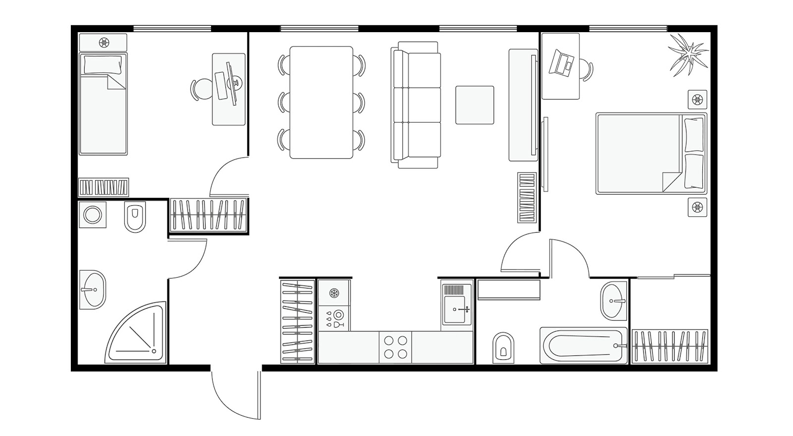
5 Most Common Types of Architectural Floor Plan Symbols
Here are some of the common standardized symbols used in blueprints:
Walls
Walls are shown using different line styles to indicate their functions. Interior walls usually have a single line, while exterior walls are shown with thicker, darker double lines to emphasize their importance.
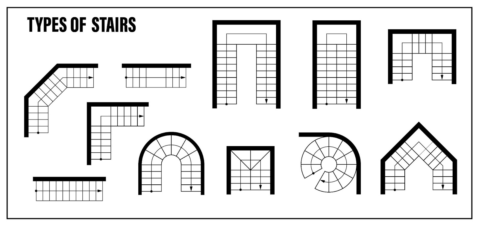
Stairs
Stairs are usually shown as parallel lines, with measurements for dimensions. In blueprints, stairs might be placed between a window, marked by a triple line with a diamond, and an interior wall, shown by a double line.
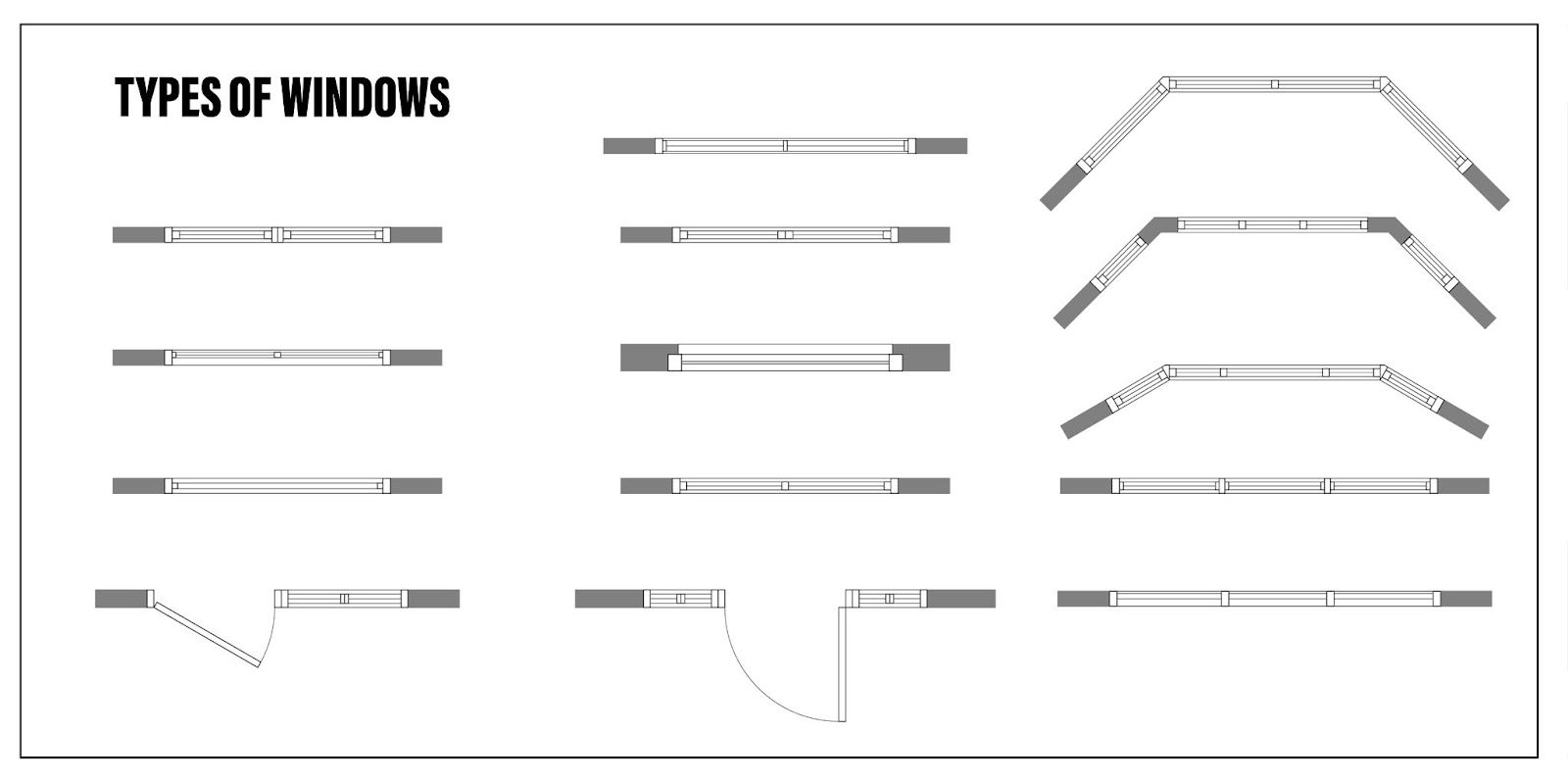
Windows
In construction drawings, windows are shown with three parallel lines, while walls use two lines. Each window is identified by a numbered diamond symbol that matches the window schedule. Watch out for common abbreviations like EQ, meaning "equal." These help show exact dimensions and placement.
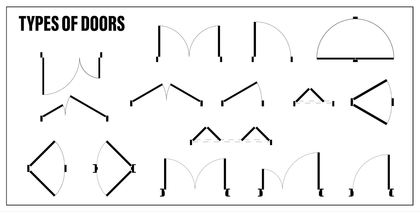
Doors
Doors on architectural drawings are usually shown with a numbered hexagon symbol. A straight line shows the door, and a curved line shows how it swings. This helps architects and designers see the space needed when the door is open, making sure the room layout works well with the door's movement.
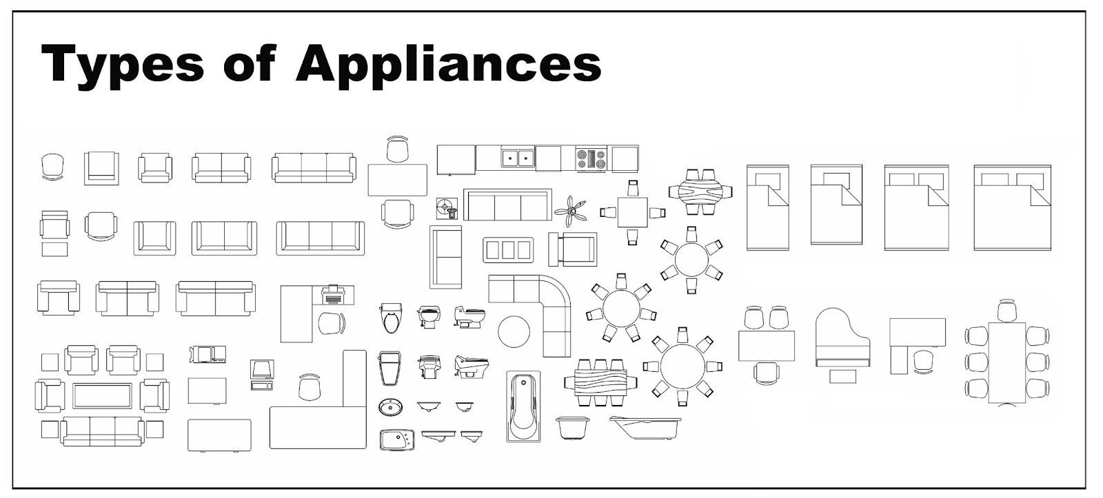
Appliances and Fixtures
Appliances and fixtures like toilets, sinks, and bathtubs are drawn to scale with thin lines to look like their real versions. Similarly, furniture on floor plans is shown with light lines, meaning these items aren't part of the structure. This helps people understand the room setup, knowing these items are just for guidance. Things like cabinets and microwaves are often shown with dotted lines to mark their spots.
Architectural Symbols Found on Other Prints
Blueprints also give detailed info on parts of the building, like outside and inside views and the ceiling plan. Here are some symbols you'll often see.
MEP (Mechanical, Electrical, and Plumbing)
The architectural plan also includes MEP drawings, covering Mechanical, Electrical, and Plumbing aspects. These drawings come with specific symbols for mechanical equipment, plumbing fixtures, and electrical systems. Builders or framers need to know these symbols to leave room for these systems during construction. The MEP prints show where all fixtures are and how these systems are routed.
Plumbing Drawings
Plumbing plans show the pipes and sewage layout. Common plumbing symbols include:- Pipe fittings: Shapes indicating ends, bends, and connections.
- Fixtures: Symbols for sinks, toilets, and showers, showing their exact spots and connections.
Mechanical Drawings
Mechanical plans cover heating, ventilation, and air conditioning (HVAC). Symbols you’ll see include:- Ductwork: Lines and arrows showing airflow direction.
- HVAC units: Marks for heaters, air conditioners, and other climate control equipment.
RCP (Reflected Ceiling Plan)
Reflected ceiling plans (RCP) give a clear view of a room's ceiling layout, showing sizes, materials, and other key information. These plans are called "reflected" because it's like looking at the ceiling in a mirror on the floor. Common RCP symbols include:- Light fixtures: Icons showing where and what kind of lighting is used.
- Ceiling materials: Patterns or shades indicating different ceiling finishes and materials.
- Air vents: Symbols showing where and what type of ventilation is used.
Conclusion
Knowing blueprint basics and how to read them is important for anyone involved in building, from architects and contractors to homeowners. This skill makes sure every part of the project, from structure to systems, is understood and done right. Recognizing common symbols and their meanings makes communication easier and helps prevent costly mistakes.
Take the Next Step with LS Building Products
Understanding blueprints is just the start. For top-notch building products, architectural drafting services, and expert help on your next project, count on LS Building Products. Contact us today to get everything you need for a smooth and successful construction process.


.jpg)

